
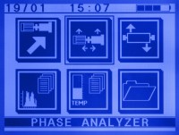
PHASE ANALISYS MODULE
Vibration phase measurement is a powerful tool for diagnosing machinery problems.
In machines with coupling, sometimes is difficult to distinguish between inbalance and misalignment based only on data from the vibration spectrum analysis, avoiding the study of some mechanical problems with certainty.
So, you would wast a time trying to balance a misaligned machine, or perform a force balancing, when in reality it is a couple problem.
To exactly know this kind of problem, the best way to take the measurement is a two channel analyzer, as offered by the DSP Logger MX300, measuring the two signals of the acelerometers without requiring a tachometer or other reference phase trigger.
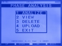
ANALYZE
The phase analysis function only requires some parameters, the equipment name and estimated RPM.
With this data, the system tunes the filters neededto perform phase analysis.
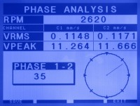
The application screen clearly shows the RPM of the equipment analyzed in real time.
The vibrational values of each point in RPM speed and 0-Peak, also include a polar plot indicating the position of the measured phase.
The phase difference between the points analyzed can be clearly seen in a window.
REPORTS
This module saves phase analysis reports, including vibratory values, RPM and measure of the phase difference.
Also stores the filtered fundamental component waveform for each channel.
REPORTING SOFTWARE FOR WINDOWS
Saves the reports generated with the phase analyzer firmware for the DSP Logger MX300.
The report shows the vibration and phase difference values of the analyzed equipment, the report also saves a graph of the waveform acquired by the system, and can generate a database containing all reports entered.
VERIFICATION EXAMPLES
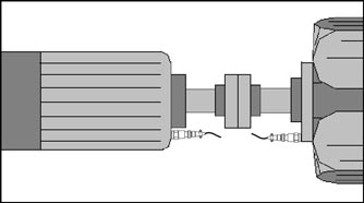
Paralell misalignment :
When looking for checking this type of failure in the equipment, sensors should be placed upright on the support points that are on both sides of the coupling, the phase difference reading should be near 180 degrees.
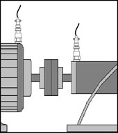
Angular misalignment :
For coupled equipments, locate sensors in axial position at both side of the coupling. If both sensors are installed en the same sense, phase difference reading would be close to 180 °. If due to construction limitation sensor are installed in opposite sense, phase difference reading would be close to 0°.
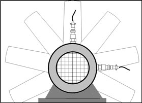
Unbalance :
To verify an unbalance, sensors must be located in radial position in such a way that they are at 90 degrees from each other (usually horizontal and vertical), phase difference reading should be near 90 degrees.
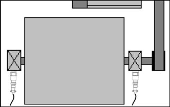
Cupla or force unbalance :
When the unbalanced rotor is wide (unbalance in two planes) shall be necessary to check if it is a force or cupla unbalance. To do that, sensors must be located at both rotor supports in the same direction (usually horizontal). If phase difference is close to 180° it will be a cupla unbalance (shall be necessary to balance in two planes), if the phase difference is close to 0°, it is a force unbalance, and can be balanced in only one plane.


Specifications
Inputs
16 bits
- Two accelerometers (50 100 500mv/g, selected by software)
- Clamp meters (10 100 1000 a, software selected)
- Two displacement (0 10 V or 10 V p-p)
- Auxiliary measure (1 VRMS, AC connection)
- Optical sensor for RPM measures and external trigger.
24 bits
- Infrared sensor.
- Passive temperature sensors (pt 100) and active (0-100°c)
- Process signals (4 - 20 mA) units designation and offset control.
- DC Voltage (0 10V) units designation and offset control..
- Displacements (0 10V) units designation and offset control..
- Auxiliary DC Voltage (0-2.5V) units designation and offset control
Output
Stereo earphone. Power 100 mW at 8 Ohms.
Features
DSP Processor ADSP 2188 , 48 MHz.
Acceleration, Velocity, clamp meter and auxiliary input spectrums
Envelope Spectrum (2 filters which can be configured)
Waveform
Overall Acceleration and Velocity: 0-Peak & RMS.
Overall Displacement Peak to Peak
Natural frequency
Phase between two channels without trigger
One and two plane automatic dynamic balance.
Frequency Response: 0.2Hz 20,000Hz
Ranges: 25Hz, 100Hz, 200Hz, 500Hz 1,000Hz, 2,000Hz, 5,000Hz, 10,000Hz,15,000Hz, 20,000Hz.
Side bands in spectra: Harmonics
Zoom in spectra
Bearing fault frequencies in envelope spectra
RMS for bands x4 or x10
Windows hanning, flattop and rectangular
Graphic spectrum: linear and logarithmic
Cursor single, harmonic, harmonic+ single, peak
Trigger: external, input channel triggering
Sealing IP 65.
USB Port for PC connection
16 Mb of FLASH memory allow storing 16,000 spectra in routes
320 x 240 monochromatic pixels LCD with LED backlight. Suitable to be used with direct solar light
Operating Temperature -10 deg C to + 60 deg C
Housing material : aluminum extrusion
Battery: NiMH 7.2 V, 3,500 mAhr rechargeable. Operating time : 8 hours
Size: 7.7 in x 7.7 in x 2.05 in (195mm*195mm*52mm)
Weight: 3.97 lb (1.80Kg.)